Shaft Alignment Tolerances: What They Are, Why They Matter, and How To Achieve Alignment Within Tolerance
Proper machine alignment is key to prolonging machine longevity, improving reliability, and reducing maintenance costs. But achieving 100% perfect alignment is nearly impossible in some setups, which is why most machines and couplings have alignment tolerances that provide a small range of allowable alignments.
This guide will explain exactly what alignment tolerances are and why they are so important when performing alignments. It will also provide practical guidance about how to achieve alignment within tolerances, and why it may be important to tighten tolerances for certain equipment.
What Are Shaft Alignment Tolerances?
Alignment tolerances are the amount of allowable misalignment, either angular or offset, between coupled shafts that won’t compromise reliability. Tolerances provide a range within which the machine can still operate at maximum efficiency and with minimal damage to components.
Shaft alignment tolerances are often determined by the rate at which the machine rotates. Higher RPMs require tighter tolerances, while slower-moving machines can have greater tolerances.
Standard shaft alignment standards are set by bodies such as the American National Standards Institute (ANSI) and the American Petroleum Institute (API). They are also specified by the International Organization for Standardization (ISO). However, individual machines may have their own alignment tolerances specified by the original equipment manufacturer (OEM).
Why Shaft Alignment Tolerances Matter
Proper shaft alignment within tolerances is critical for ensuring the longevity and efficiency of rotating machinery. When shafts are misaligned beyond acceptable limits, excessive forces are transmitted to bearings, seals, and other components, leading to increased vibration, heat, and wear. This can result in premature equipment failure, costly downtime, and higher maintenance expenses. Sticking to strict shaft alignment tolerances minimizes these stresses, extending the service life of the machine and its components.
Additionally, precise alignment enhances operational efficiency. Misaligned shafts can cause energy loss due to increased friction and vibration, reducing overall system performance and increasing utility costs. For couplings, proper shaft alignment ensures they function within their design limits, preventing excessive wear or failure.
Beyond equipment damage, misalignment in critical assets can pose safety risks, such as unexpected failures in high-speed turbines or compressors, making precise alignment essential for worker safety.
Finally, achieving alignment within tolerance also improves key performance indicators like Mean Time Between Failures (MTBF) and Mean Time to Repair (MTTR), optimizing performance and minimizing operational costs.
Types of Shaft Misalignment
Misalignment comes in two forms: offset (also known as parallel, when shafts are shifted apart) and angular (when shafts are tilted relatively to each other). Alignment tolerances provide the maximum allowance for both misalignment types.
Parallel or offset misalignment tolerance is measured in tiny units, called mils. One mil is one one-thousandth (or 0.001) of an inch, about the width of a human hair. This small amount may be indiscernible to the naked eye, but just a few mils can mean the difference between a machine that’s aligned within tolerance or one that is misaligned.
Angular misalignment is measured in mils per inch, which describes how much the shafts tilt apart over a given distance. For example, a 1 mil/inch angular misalignment means the gap between shaft centerlines grows by 1 mil for every inch of length.
Other Factors Affecting Tolerances
As we previously mentioned, shaft alignment tolerances depend on how fast a machine spins and how it behaves during operation. Speed-based shaft alignment tolerance charts provide guidelines for acceptable misalignment based on the machine’s rotational speed. These charts, often provided by manufacturers or industry standards, ensure alignment matches machine demands, reducing wear on bearings, seals, and couplings.

Thermal Expansion
Machines also change during operation due to thermal growth and operational loads. Heat causes metal components to expand, shifting shaft alignment, while forces like torque or piping stress can cause further movement. To counter this, technicians perform cold alignment, intentionally setting shafts slightly misaligned to account for expected changes so they align perfectly when the machine is running. For example, if a motor rises 4 mils when hot, it’s aligned 4 mils lower when cold. Modern laser alignment tools simplify these adjustments by factoring in thermal growth data.
Shaft Alignment Tolerances vs Coupling Alignment Tolerances
It’s also important to note that there is a distinction between shaft alignment tolerances and coupling alignment tolerances. Shaft alignment tolerances protect the machine itself, along with components such as bearings and seals. Coupling alignment tolerances protect the coupling, and so coupling alignment tolerances may differ from shaft alignment tolerances.
Coupling alignment tolerances are often greater than machine alignment tolerances, especially for flexible couplings. However, for certain types of rigid couplings, the coupling may have tighter tolerances than the shaft. Aligning shafts themselves will generally put coupling alignment well within coupling alignment tolerances.
What To Do When “Within Tolerance” Isn’t Enough
Alignment tolerances are typically expressed as a number that represents the maximum offset that could still be considered within tolerance. For example, a tolerance for a machine might be 8 mils offset and 0.5 mils/inch angular misalignment tolerance. This means that while 8 mils and 0.5 mils/inch are within tolerance, anything less is also in tolerance.
In most cases, the smaller the misalignment is, the better the machine will operate. So, while an alignment that’s offset by just 8 mils may be within tolerance, an alignment of 6 mils, 2 mils less than the stated tolerance, would be even more optimal.
For many machines, following published tolerances from manufacturers or industry standards ensures reliable operation. These tolerances are designed for general applications where minor misalignment doesn’t significantly impact performance. They balance precision with practical considerations like alignment time and cost, making them suitable for non-critical assets or standard operating conditions.
However, for critical assets such as centrifugal compressors in refineries, generators in power plants, or high-speed spindles in manufacturing, tighter alignment specifications can significantly improve longevity and minimize downtime. Critical equipment often operates at high RPMs or under demanding conditions (such as continuous operation, high torque, or in harsh environments), where even small misalignments can amplify vibrations, stress bearings and seals, or lead to catastrophic failures. Tightening tolerances beyond published standards reduces these risks, enhancing reliability and safety.
Deciding when to tighten tolerances involves weighing the benefits of a more precise alignment against the effort of achieving and maintaining the alignment.
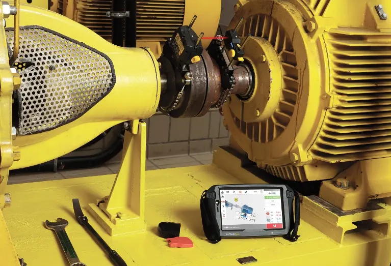
Aligning Within Tolerances, the Easy Way
Technicians achieve alignment using tools like dial indicators, which measure misalignment as shafts rotate, or advanced laser alignment systems, which provide real-time data and automated guidance for precise adjustments.

Pruftechnik single laser alignment tools come with built-in alignment tolerance tables to help you easily comply with ANSI standard specification tolerances. Simply select the coupling type, coupling format, diameter, and the RPM of the machine, and the alignment system will deliver a table showing three alignment tiers — minimal, standard, and precision. Minimal alignment is just within tolerance, while precision alignment exceeds tolerance standards and is the most precise alignment possible.
Then, simply take measurements by rotating the shaft, get real-time results, and follow the automated, guided workflow until you achieve alignment within tolerance.
For machines that require tighter tolerances than standard, Pruftechnik tools also allow users to define their own tolerances, including asymmetric tolerances, to achieve the alignment needed for their specific application. Technicians can use an RFID tag to tag the machine, and Pruftechnik tools can read the RFID, connect to the cloud, and pull in historical alignment data, including user-specified tolerances, for faster precision alignments.
Alignment tolerances tell technicians how close alignments need to be, but Pruftechnik tools make achieving alignment within tolerance easy, even for technicians with no prior experience. Learn more about Pruftechnik laser shaft alignment tools here.


